Clif's Astronomy Site
Building my Schupmann Medial Telescope
I have been interested in catadioptic and tilted component telescopes for many years, but particularly in the wonderful but somewhat neglected telescope invented by Ludwig Schupmann around the end of the 19th century. The telescope combines reflecting and refracting elements (hence catadioptric) and achieves achromatism to a very high degree while using a single variety of optical glass.

To see how this is done, consider the schematic drawing of the optics of a Schupmann Medial telescope shown at the left. White light from the distant object enters the objective at the top. The objective is a simple lens, usually constructed of a good optical variety of borosilicate crown glass, such as BK7, but it could be made from any optically homogenous glass. Curves are picked to give a modest focal ratio in the f/10 to f/20 range with a bending (distribution of power between the front and back surfaces) giving the minimum coma or OSC (offense against the Sine Condition). This gives an unsymmetrical double convex lens with the stronger surface facing the object. Since the objective is made from glass that has a different refractive index for different wavelengths, white light does not focus to give a sharp image. The long wavelengths focus further from the lens than the short wavelengths. If you tried to put an eyepiece behind this "focus" you would be very disappointed by the rainbow fringed images of the stars and planets. Right in the middle of this sloppy image we place a concave spherical field mirror, somewhat larger than the desired size of the final image. The field mirror forms a real image of the objective lens upon the next optical element, a mangin mirror corrector. In the design shown, the mangin is half the size of the objective and is placed halfway between the objective and the lousy focus just described, but moved out of the optical path of the rays coming from the objective to the first focus. In order to put the image of the objective on the mangin corrector, the field mirror is tilted slightly to the right. The focal length of the field mirror is picked to give a 2:1 reduction in image size. The distance from the mirror to the objective is F, the focal length of the lens in yellow green light and the distance from the mirror to the mangin corrector is F/2. From the lens equation we can calculate the focal length of the field mirror to be one third of the focal length of the objective, hence its radius of curvature is 2/3 the focal length of the objective.
The mangin corrector is made of the same kind of glass as the objective, preferably from the same melt of high quality optical glass, but it would probably work with two pieces of plate glass cut from the same sheet. The front concave surface is curved to give -1/2 the optical power needed to exactly cancel the positive refractive power of the objective. Since the light traverses this surface twice on the way to the final image, complete cancellation occurs. This cancellation happens for all wavelengths. The back convex surface of the mangin corrector is silvered and has a curvature such that reflection from the inside of the silvered surface allows a second image to be formed at the distance of the field mirror. We tilt the mangin slightly to bring the image out of the optical path where it can be picked off by the small diagonal mirror and directed to the side to be viewed with an eyepiece or focused on film or a CCD surface. Because of the exact cancellation of refractive power at all wavelengths, this final image is perfectly achromatic. I don't mean in the sense that it has two wavelengths (as in conventional achromats) or even three wavelengths (as in apochromats) having the same focus, but that all wavelengths are brought to the same focus, just as they are from the mirror of a reflecting telescope. The small tilt of the mangin corrector introduces astigmatism in the final image. This is corrected by tilting the objective a small amount. Since it was made at the coma free bending, no coma is introduced by this tilt.
In the design shown, the mangin corrector is half the size of the objective, but it could be made smaller or bigger. Often it is made the same size as the objective. This results in a somewhat wider well corrected field of view. There is a special case where the corrector diameter is around 55% of the size of the objective where all the surfaces can be made spherical. We call this the Super Schupmann. When the corrector is smaller or bigger than this magic size, one of the surfaces (usually R2 of the objective) is figured to an aspheric to cancel marginal and zonal spherical aberration. The 13" f/10 Schupmann at McGregor Observatory at Stellafane is made with the magic corrector size and has all spherical surfaces.
I had wanted to build a Schupmann since I first learned about the design’s wonderful features back in the 60’s. Over the years since, I never quite got up the ambition to make a Schupmann myself, however, in 2005, I learned that my buddy Jim Daley had an available set of 7.25” f/14 Schupmann optics, languishing on the shelf of his basement optical shop. This set was from his first Schupmann, made with a 50% corrector. Both the objective and corrector were figured so that both the intermediate focus and the final focus were corrected for spherical aberration. With great foresight, Jim had built the tube oversized so he could also use it for his second Schupmann, a 9” f/11 design of the same focal length. The objective and corrector cells he had originally made for his telescope were also available since they could not be used with the 9” f/11 design. I purchased the optics and cells from Jim and proceeded to get busy building an optical tube to house them.
The design for this Schupmann medial was computed by Ed Olson and is shown below.

Note that no tilts are specified. They are not critical to the design since the coma contributions of all three elements are zero: the objective has the coma free bending, the field mirror is in or close to a focal plane and the mangin correctore is working at 1:1 imaging. The corrector is simply offset the minimum amount to clear the outer rays from the objective to the field mirror, and the field mirror is tilted whatever amount is required to center the image of the objective on the corrector. As I constructed the telescope, the offset of the corrector was 5.92 inches and the tilt angle was very close to 4.00 degrees. Although the offset of the corrector is somewhat arbitrary, the adjustment of the tilt angle of the field mirror to make the image of the objective coincide with the corrector is not arbitrary. It fact, this adjustment is done at the beginning of each observing session by tweaking the micrometer screws of the field mirror cell until no color fringes are seen around bright objects. This adjustment is easy and is as intuitive as focusing the image. When making the adjustment one automatically tunes out atmospheric dispersion. This adjustment may be made as often as needed to correct for variation of atmospheric dispersion as the altitude of the object changes over the course of an observing session. The corrector itself is tilted only enough to move the final focus away from the field mirror enough so it can be picked off by the small diagonal mirror. This tilt, whiile it does not introduce any coma, does introduce astigmatism and should be kept as small as possible. In the telescope as I constructed it, the tilt of the corrector was 0.73 degrees. The astigmatism introduced is cancelled by the appropriate tilt of the objective lens. The results from a ray trace of this design using the program OSLO is shown below,(with the appropriate tilts supplied to the program). Note that the design should be diffraction limited over a field of view greater than 0.1 degrees. The black outlined circle is the size of the Airy disk.

The first step in building a telescope of this type is to make a scale drawing and then a full size layout. I did the scale drawing in my computer using MacDraw Pro, and, since I decided to build it using a 1/2" square wood stick framework with a skin of 1/8" Luan mahogany plywood, I did the layout directly on the plywood used to make the sides of the tube. The scale drawing of the optics and the side view of the tube structure is shown below..
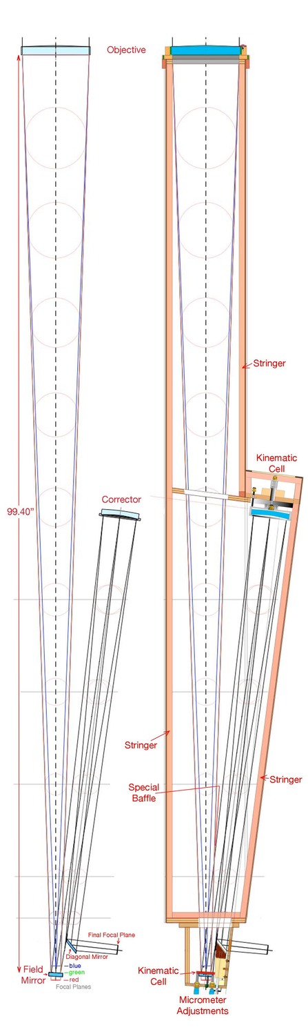
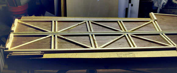
My plan was to borrow some techniques from model airplane building and make the tube from longitudinal stringers cut from selected Douglas fir lumber, see cross section below, and 1/2" square cross pieces and diagonal braces, and cover the whole thing with 1/8" Luan plywood. Strengthening bulkheads containing the baffle holes were made from 1/2" thick birch playwood. A typical cross section of the tube is shown below left and typical bulkheads are shown below right. The bulkheads in the back half of the tube must have complex baffles to accomodate all three light paths, from the objective to the field mirror (green tint), field mirror to corrector (red tint) and corrector to final focus (gray tint). Note that the stringer cross section provides a couple of 1/8" deep pockets in which to glue the Luan and seal up the plywood edge grain.

After placing the Luan plywood side pieces on a nice flat table, inside surfaces up, the stringers, cross pieces and diagonal braces were glued into their laid out places using light brad nails as temporary fasteners to hold the wood strips in place. Note the 1/2" wide sockets for the bulkheads formed by the cross pieces in the photo below:
After the glue holding the strips to the Luan had set and the temporary brads pulled out, the bulkheads were glued into place, first on the right side panel,

and then the left panel was lifted off the table and its sockets carefully fitted over all the bulkheads before the glue had completely set so that adjustments could be made to keep the assembly square and then securely clamped together. It is nice to have a lot of clamps on hand. This assembly is shown below. Note the two sets of baffle holes, one tracing out the light path from the objective to the field mirror and the other tracking the light path from the corrector to the final focus. Scallops from the tops of the first set of baffles and the bottom of the second define the light path from the field mirror to the corrector.

Note that the baffle holes you see in the plywood bulkheads are not the actual limiting baffles. These were made from thin aluminum flashing sheet with inside diameters cut to the precise size indicated by the scale drawing (smaller than the holes in the wood), and attached with tacks to the front side of the bulkheads. There is one other baffle that is difficult to show properly. It is a strip of Luan with a U-shaped cutout placed between baffles 2 and 3 (counting from the eye end) and attached to them. Black thread is strung across the cutout and forms the thin edge of the baffle where the beams separate. This small baffle is roughly parallel to the long axis of the tube and its front edge is located where the beam from the objective to the field mirror and the beam from the field mirror to the corrector separate. It is shown as a red line on the scale drawing layout above. This baffle obstructs the view of a small crescent shaped segment from the edge of the objective lens and prevents possible flooding of the field of view by a bright object that just happened to be in the wrong place in the sky. In the picture below we see the special baffle in place with a u-shaped section with black cotton thread strung over it. On the right side we are looking through the first baffle up the tube. The threaded section is completely opaque when seen from this shallow angle and does not reflect any appreciable light. The green shaded area is where the corrector will be and the pink shaded area is where the objective will be on the other side of all the baffles, The special baffle prevents us from seeing the objective from the lower edge of the final image. After this picture was taken, the interior of the tube was painted flat black with a spray enamel.

The Tailpiece. At the back of a Schupmann is a critical componet with lots of fiddly bits. this is where the field mirror in it's kinematic, micrometer adjusted cell lives, as well as the diagonal to pick off the final corrected beam and direct it to the focusing mechanism and eyepiece holder.
The scaled drawing below shows a cross-sectional side view of the tailpiece. The diagonally hatched parts are aluminum plates held together by small screws and 1/2" square aluminum stock (dotted lines). The reversed Crayford focuser shown is motorized for remote focusing while looking at the computer screen at an image from a camera. The diagonal mirror alignment is by a tilt tip adjustment with Allen screws on the top plate and rotation by the shaft extending through the back plate.

Below is a back view of the tailpiece showing details of how the kinematic field mirror cell and moveable shutter would look if the back plate were transparent. In blue is a sketch of the shutter in the normal open position, and in red it is shown in the closed position ued for collimation of the mangin mirror. The three supporting ball footed screws are also shown. Note that only the yaw an pitch adjusting screws have fine micrometer threads. The central screw is only used for axial movement of the field mirror, the micrometer screws adjust the field mirror in pitch and yaw and provide a sensitive adjustment for removing lateral color and atmospheric dispersion.

Below is a detailed drawing of the field mirror cell itself. It was constructed in a three step operation in which an eccentrically mounted 3.5" square, 1/2" thick piece of aluminum is first turned on the lathe to make the cylindrical parts of the cell, including the internal thread for the retaining ring. After the lathe work, the piece is bandsawed to remove the excess stock and form the paddle arms. The final step is done on a milling machine. In this both paddles are machined flat and the vee-groove added to the yaw adjustment paddle. The hole for the tensile spring is also drilled. The externally threaded retaining ring is made in one setup on the lathe. The field mirror rests uncoated side down in the cavity of the cell and the retaining ring screwed into place, just barely touching the aluminized surface of the mirror so it does not rattle.


To the right is shown the central support for the field mirror cell. It is just a short piece of 7/16" threaded rod with a ball bearing epoxied to a center drilled hole in one end. A locking nut is also shown. It has a slot in one end for a screwdriver.
Below and to the left is a detailed cross sectional view of the field mirror cell kinematically mounted on the rear plate of the tailpiece. The ball footed screw is not shown in the drawing. This screw is only used for changing the separation of the field mirror from the objective.

Working against the central pivot, the two micrometer screws shown in the drawing bear on orthogonal paddles on the cell. The paddle on the horizontal arm has a vee-groove and provides adjustment in yaw when its micrometer screw is turned. The other paddle on the downward pointing arm is flat and provides adjustment in pitch when its micrometer screw is turned. The careful adjustment of these two micrometer screws not only adjusts the lateral color out of the image, but can even tune out atmopheric dispersion. The adjustment is made whlle looking through the eyepiece or looking at the focused image from a camera on the computer screen. Simply adjust the screws until all color fringes disappear. There is also a shutter with a central pinhole which may be moved into the light path during the initial collimation of the mangin mirror. Other than knocking a spider web out of the way, there is no other use or the shutter rotate knob.
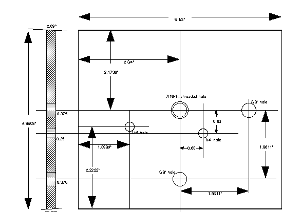
Below is a drawing of the front plate of the tailpiece, cut out from a 7" square piece of 1/4" aluminum. The location of the remainder of the tailpiece is shown by dotted lines. Screws through the corner holes hold the whole tailpiece onto the rear wooden bulkhead of the tube structure.

Below is a drawing of the back plate of the tailpiece. It is made from a sheet of 1/2" aluminum plate. Note bevel angles on top and bottom edges. The 7/16" threaded hole is for the center pivot screw. The ball tip and conical depresion in the back of the fiel mirror cell define the location of the field mirror with respect to the objective. The undreaded 3/8" holes are for the micrometer screws that bear on the vee-groove and flat surfaces on the paddle arms of the cell. The 1/4" hole is for the end ring of the tensile spring to pull through to be held in place by a retainer pin.
Below is shown a sketch of the side plates. They are held onto the other components of the tailpiece by 6/32 countersunk oval head screws and tapped holes in the other pieces. It is made from 1/8" aluminum sheet.

Below is a sketch of the bottom plate, made from 1/2" aluminum sheet. Note the bevel on the back edge.

And finally, below is a sketch of the top plate showing the hole for the focused beam from the telescope to get out into eyepieces or cameras. A dotted line representation of the tilt/tip plate for adjusting the diagonal is indicated.

A couple of views of the finished tailpiece are shown below.


----------- TO BE CONTINUED ----------


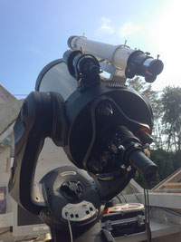
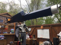
In June of 2018 I did a complete cleaning of the white painted wood tube to remove dirt and what appeared to be mold growth on the paint. I repainted it Royal Blue using acrylic latex containing a mildewcide. Here it is mounted on the Astro-Physics 1200GTO mount in Observatory #3:

Note new sliding weight on the underside of the objective end of the tube. This is to permit critical balancing of the tube about the declination axis. You can also see the video finder mounted on the top side of the tube just in front of the hump containing the mangin corrector. The finder is made from a 50 mm lens from a SLR camera coupled to an ASI120MM CMOS video camera with a T-mount thread spacer. Works great!

Weight is a 2" length of 2" ID aluminum tubing with a 2" diameter disk of 1/2" aluminum plate pressed into one end. When filled with melted lead, bored out to 5/8" and fitted with a flexaframe foot flange it makes a nice 2 lb balancing weight for added cameras, filter wheels or other accessories, and it was all made from scrap and stuff in my junk box!


The C14 retired from Jenny Jump


Mars Sept 8, 2020